Star Wars fans will always remember the thrill of their first introduction to light sabres, the oh-so-cool laser swords. Though maybe not as exciting, laser scanning procedures in construction have a certain sci-fi appeal too. When 3D laser scanning techniques are used to help create as-built drawings, fantasy meets cold hard reality with oomph. The concept of creating manual as-fitted drawings may seem lacklustre in comparison to laser-scanned as-fitted drawings for a number of reasons.
First, though, let’s try to understand what as-fitted, or as-built, really means. Often used interchangeably, there are a few technical reasons why as-built, record and measured drawings are different.
- As-built Drawings: Typically prepared by the contractor on original construction documents and drawings, the as-built changes are made in red ink.
- Record Drawings: Prepared by the architect based on the contractor’s changes, record drawings mark the notes of the contractor’s on-site changes in the as-built drawings and are made specifically for the owner.
- Measured Drawings: Prepared for already existing buildings during a renovation, these drawings are derived from measurements of a standing building and are created from on-site project data.
As projects may run off course during construction, it is vital that project contractors keep precise and updated records of changes or variations to the original design. As-fitted drawings are records of those changes and consist of:
- A revised set of construction drawings that documents all changes made to specifications and design, showing exact dimensions and actual locations of all elements
- Also known as red-line drawings, they include all modifications, design changes, change orders, additional work, etc.
While creating manual as-fitted drawings, some of the guidelines are as follows:
- All specific information used during construction must be written down.
- When adding details, the same scale must be used as in the original drawings.
- Score lines or an ‘X’ is drawn through old values.
- New values are included in notes made in margins.
- Exact details of changes or additional information for fabrication, erection, installation, location, sizing, material, dimension, etc. are written down.
- All necessary data on the contractor’s design systems are manually noted, such as elevations, grade modifications, piping utilities, earthwork, etc.
- Every sheet that has changes must include a date in the upper right-hand corner.
- Additional sheets must have the same scale and legend as the one that is being replaced or referenced.
- Handwritten notes on the drawings must be clear.
- Revision notes and corrections must be manually added to affected section views, general notes, specific notes, profiles and schedules. This requires consistency and must have the same figure or shape to denote changes or revisions.
- Add shop drawings into an appendix.
- Update the index sheet to show all the latest drawing changes.
Laser-scanned As-fitted Drawings
Presenting an easier, more accurate alternative to creating manual as-fitted drawings, laser scanning replaces tape measures, clipboards, calculators and other manual surveying tools. An accurate image of a building is created with exact measurements derived from the scan.
Software can be used to create as-built drawings and can add photos, other information and track changes on the site immediately, helping to avoid errors and save money and time.
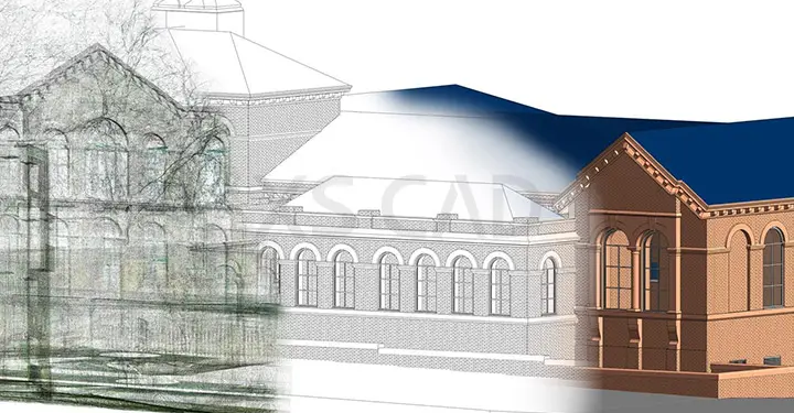
Laser scans are precise and developed at high speed into a point cloud, generating near-perfect 3D images of both external and internal surfaces. In general, the benefits of laser-scanning for as-built output are:
- Accurate, realistic models of existing buildings
- Ability to view plans in 2D and 3D for clear understanding
- Two-way integration with QFM, so that updated assets will automatically be seen in the 3D model
- Models can be created from existing drawings and digitised to add data, so they can be searched, scaled, read and measured.
- Eliminates travel to the site
- Ability to make informed decisions quickly
- Costs associated with hot working, construction rework and field fit-up welds are minimised.
- No need to manually write down specific details.
- Scans are captured with the same scale.
How does it work?
- A laser scanner uses a volumetric measurement device to generate 3D data.
- The scanner is put on a tripod, and a laser rotates at high speed to capture points of data from the surrounding site.
- The relative position between the surface and scanner is recorded as X, Y and Z values, known as a ‘point.’
- Millions of these points create a precise 3D digital picture, a cloud of points that become a point cloud model.
- Scanners can also capture colour images, which generates coloured representation of the scanned data.
- Software displays the scanned data in standard 3D CAD applications for dimensional extraction, creating 2D drawings and eliminating clashes, from any location.
- CAD models can be directly superimposed on to the laser-scanned model to assess design accuracy and installation readiness.
- Laser-scanned data can be used to develop piping and instrumentation diagrams, steel framing plans, piping isometrics, plan drawings and elevation drawings.
Scan to BIM
Scan to BIM (Building Information Modelling) is a process of capturing scanned data from the real site conditions in the form of a 3D point cloud model with the help of a scanner and creating a BIM model. This is useful for renovation projects, retrofit and conversion projects.
It extracts accurate, precise construction data from existing buildings. Scanned data includes geometry, mesh modelling, topography extraction, etc.
- A scanner captures data from the visible surfaces. For a clear 3D digital model, multiple scans are taken from different directions and angles.
- All scans are registered into a single point cloud. We can use point cloud software to register, review and model the data.
- The point cloud is imported into the 3D modelling software, such as Revit, and a BIM model is created.
- The higher the density of the point cloud, the greater the accuracy in geometry.
Why Contractors Like Laser-scanned As-built Drawings
- The drawings are accurate.
- Missing elements can be easily added.
- It results in less rework from human error – 3D laser scanners can capture all the essential information about a building. Any measurement can be gathered from the scanned data or point cloud model.
- It helps evaluate documentation throughout construction – Any changes can be made quickly, tracked and be sent as a scan to stakeholders, helping to track updates and keep teams on schedule.
- It helps reduce costs and keep to schedules.
- It captures high-precision data – Data helps generate an accurate point cloud model, eliminating the potential for human errors, thus completing tasks efficiently.
The point cloud to BIM process saves time in creating as-fitted or as-built drawings when compared to creating manual as-fitted drawings. The construction cost can be reduced to a certain extent as the BIM model helps identify relevant areas of work early in the design phase, generate energy analysis and ensure a higher quality of the work on site. With the support of BIM specialists who clearly understand 3D laser scanning and Scan to BIM processes, high-quality, cost-effective, laser-scanned as-built drawings can be generated easily, reliably and within deadlines.
XS CAD has valuable experience providing 3D BIM modelling services and as-built drawings for architecture, engineering and contractors. Our range of services for structural, architectural and building engineering firms, such as consultants and contractors across the world, include 3D BIM modelling, as-installed drawings, and BIM MEP services. We have proven to be a preferred Revit BIM outsourcing partner, due to the high quality and clash-free 3D models, created by using Revit, AutoCAD, and BIM Collaborate Pro for cloud collaboration.