
Our Articles
Exploring LOD in Architecture & Engineering
Terminology in any industry is a sign of growth. In the construction industry, new terms crop up with regularity and older terms adapt or are modified to encompass new realities. One such term used extensively in the AEC industry is LOD or Level of Detail or Level of Development. Within a world managed by Building Information Modelling (BIM) and BIM services, LOD is a universal term used to describe and explain how precise a model is and what it lacks in terms of architectural BIM modelling.
The term LOD references the input of the model. For example, LOD, or Level of Detail, can identify specific shapes and measurable locations of steel pipes in a model.
Speaking of Level of Development, this refers to the depth of thinking applied to a model, or how reliable a model is. For example, the Level of Development can specify whether the pipes in a model have been engineered and it can mention how permanent their placement is.
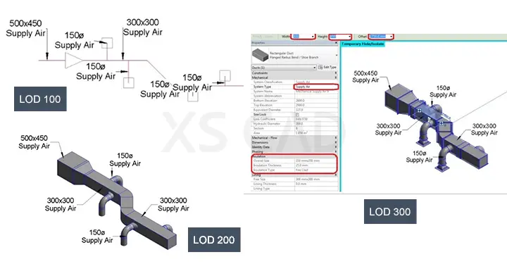
When a component is developed to increased levels, then more detail is provided also.
Architects and consulting engineers have moved from AutoCAD to Revit. But several MEP contractors still work in AutoCAD. With Level of Development (LOD) standards, an MEP contractor knows what to expect from the owner, architect and consulting engineers, regardless of the software being used.
So, what is the most efficient method of progressing a model from the architect and consulting engineer’s LOD 200 to construction LOD 400?
An interpretation of the AIA defined Level of Development is as follows:
Contractors are more likely to bid projects from an LOD 300 drawing or model.
Virtual Design and Construction (VDC) can be achieved at LOD 350, but the potential for profitability occurs at LOD 400. This is because LOD 400 allows for the planning and virtually practices how to fabricate and later install each component.

With LOD 400, confidence in prefabrication is gained, completion of milestones can be tracked with the scope and changes to the scope can be identified and documented. It is vital to have the right skillset, software and access to the right data to achieve LOD 400.
Contractors may sometimes use generic, highly detailed models that lack other relevant data. Using models from manufacturers or model-sharing websites needs a lot of work to add the development data needed for a streamlined workflow. These challenges can be eased with the right partners to support the development of models using Revit 3D BIM modelling.
Viewing 3D city models on mobile devices (smart phones and tablets) enables informed planning, augmented reality projects, real estate sales and 3D navigation. In today’s world, 3D datasets are used for research and in real life applications. Applications include determining illegal residential buildings using heat sensing equipment and using 3D mapping to help town planners with noise mapping. It is important to be able to access 3D data and integrate it with 2D data, while displaying the data on a mobile.
Increasingly, detailed, realistic 3D features, such as full roof structures rather than small blocks or individual buildings resulting from computer-aided design (CAD) models or terrestrial LiDaR (Light Detection and Ranging) or other scanning, are made available.
Both flat roofs and detailed 3D structures result in vast amounts of complex 3D data, which may not be easy to visualise. To better understand performance implications, it is useful to generate 3D city models with different levels of detail (LOD) – ranging from LOD 0 – 4:
To know more about Architecture & Engineering . . .
This detailed and complex data can be generated from digital ortho-photos, computer-aided design (CAD) models, LiDaR point clouds or terrestrial laser scanning. For more depth in detailed modelling, it is BIM modelling based on CAD or Revit BIM 3D modelling tools that are required. It is pertinent for design support providers to clearly understand and provide high-quality 3D models through architectural BIM modelling and recognised BIM virtual construction methodologies.
XS CAD has valuable experience providing Revit 3D BIM modelling services, architectural BIM modelling and other BIM services for general contractors and consultants. Our range of services for consultants and manufacturers across the world include BIM modelling, creating models and drawings by using Revit BIM, AutoCAD and BIM Collaborate Pro for cloud collaboration.