Our Articles

MEP Fabrication Modelling Challenges
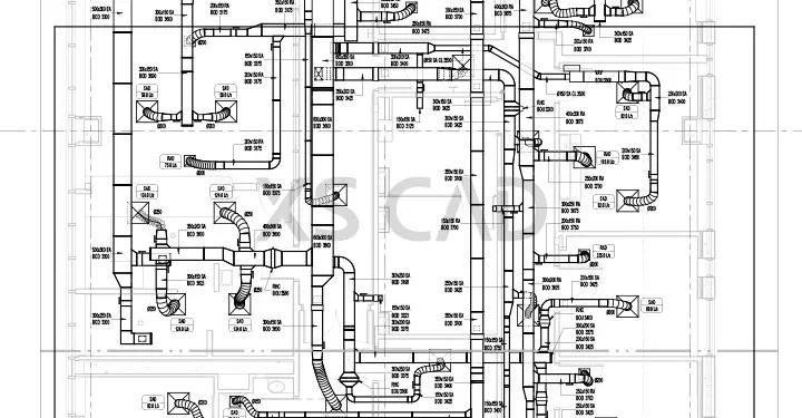
It’s important to maintain the momentum while moving two steps forward with advances in the construction industry. Pushback may occur at times, and the challenges faced by MEP (mechanical, electrical, plumbing) fabrication modelling can be met and overcome with modern, upgraded software. The MEP fabrication modelling process is widely used in commercial and residential construction projects because it improves project schedules, saving costs and improving on-site productivity, safety and space utilisation by shifting the fabrication process offsite. Prefabrication modelling offsite requires detailed and accurate MEP (M&E) prefabrication models and fabrication shop drawings which are not only installation-ready but should also be machine-ready for fabrication.
There are several project stakeholders who play a specific role in the MEP fabrication modelling process, such as:

The entire workflow of MEP fabrication modelling, due to its several stakeholders and processes, can be a challenging process.
Challenges to the MEP Fabrication Modelling Process
Collaboration between Teams
The MEP fabrication process requires the collaboration of multiple stakeholders. This collaboration has a significant impact on the cost, time and resources allocated.
Integration of Different Processes
Ideally, to avoid cost overruns, save time and utilise resources strategically, the designer, general contractor, MEP contractor or consultant must adopt a top-down approach in the fabrication process. They must define, identify and implement an approach that enables integrating the work of MEP fabricators, installers and manufacturers of MEP components.
Compatibility of MEP Fabrication Software Programs
Autodesk Fabrication and Revit MEP are two main MEP fabrication software programs that have MEP fabrication detailing features. Challenges arise because MEP (M&E) prefabrication models and drawings need to be compatible to have direct machine interface (DMI). Revit MEP is widely used, as it is more economical than Autodesk Fabrication. However, it is not compatible with DMI. While fabricators and manufacturers may require models in Autodesk Fabrication format (required for machining), most fabrication modelling companies use the fabrication features of Revit MEP, producing an incompatible format. Converting Revit-based fabrication drawings to Autodesk Fabrication models involves more than 30 percent rework, which leads to delays, cost increase and may result in component fabrication errors.
Inaccessibility to Content Libraries
Access to country-specific content libraries can be accessed on Revit MEP only if Autodesk Fabrication is installed. This is a challenge for fabrication designers who require fabrication configurations when developing Revit MEP fabrication models. While Revit has default fabrication content libraries which contain basic generic MEP parts, access to associated product data and fabrication content, such as generic UK Metric and US Imperial content, required to develop an MEP fabrication model is accessible only when Autodesk Fabrication CADmep is installed. If Autodesk Fabrication products, such as CADmep, ESTmep and CAMduct, are available, fabrication configurations can be listed and used within Revit.
Rework of Issue Drawings
Conventionally, MEP consultants develop plans and schematics, which are then submitted to the contractor for detailing, spatial coordination, fabrication and installation. In most cases, the MEP contractor has to rework these drawings to create issue drawings, or 3D M&E (MEP) coordinated drawings, for fabrication, which must be clash-free, installation-ready and suitable for fabrication.
So, is there a way out of the dark tunnel of MEP fabrication modelling challenges?
Evidently so. Autodesk’s fabrication tools can help MEP stakeholders in a project export an MEP model for design, estimation and the fabrication of mechanical systems, such as ductwork, pipework etc.
When the fabrication tools are linked to the Revit MEP model, designing, material management, installation, estimation and the downstream fabrication process becomes significantly easier. The tools help generate the ductwork network, create slope pipes, vertical annotation, etc.
Design-intent Revit models can be developed into a detailed fabrication model in Revit MEP, using Autodesk fabrication product content. These detailed fabrication components contain data for estimation, prefabrication, construction and installation processes. Fabrication tools can be used to update or modify the fabrication models and eventually generate shop drawings.

Cutting sheets of gauges for manufacturing vendors is made possible by extracting flat patterns from 3D models using fabrication tools. Autodesk software Fabrication CAMduct can be used for manufacturing and ductwork fabrication. It’s features include:
- Sheet metal and linear nesting
- Shared content library
- Bar coding and QR coding
- Duct fabrication component library
- Labels and worksheets
Facets of M&E design engineering (MEP) have progressed substantially to meet the challenges of MEP fabrication modelling in recent times, and building projects have found several benefits to fabricating MEP components and even larger MEP items, such as prefabricated bathroom modules. Costs can be saved, on-site productivity has been shown to improve, project schedules are met on time and there is an improvement of on-site safety for both equipment and workers. Using MEP fabrication modelling and fabrication drawing services provides firms with a competitive advantage in the construction industry to deliver projects on time and within budgets.
XS CAD has valuable experience as a prefabricated models and drawings, BIM modelling services provider, providing Revit 3D modelling services, M&E (MEP) design engineering, MEP fabrication modelling and fabrication shop drawings for global AEC firms. Our range of services for designers, architects and contractors across the world include 2D MEP drafting, 3D BIM modelling, MEP coordination and fabrication drawing services.

