Our Articles

What’s in a Homebuilding CD Set?
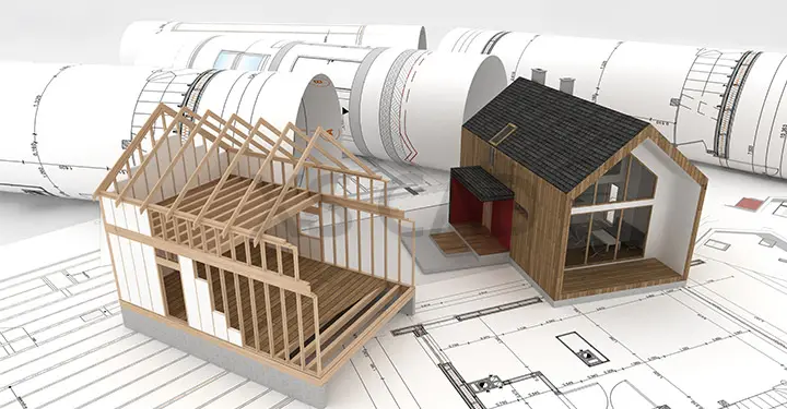
One of the key pre-construction design deliverables powering the AEC (architecture, engineering and construction) industry, construction documentation sets, or CD sets, are kaleidoscopes of design information vital for cost-effective, safe, professional and comprehensive construction. They contain vast swathes of information necessary for a clear presentation of construction design. We briefly consider the details included in such residential construction drawings.
What is the function of a set of construction documents?
Construction documents are also called a drawing set or a sheet set. They are a set of documents shared with customers, architects, engineers and other construction stakeholders to plan and communicate design. These documents, along with construction schedules and material takeoffs, are necessary to complete the design. Construction documentation consists of several different sheets, each including drawings and schedules.
Preparing construction documents or the CD set is the final phase of the design process. The CD set accurately documents building design in accordance with local building codes and for the final set of design options selected by a customer. Creation of the CD set begins following schematic and developed design stages where plans and costs have been agreed for the project. During this phase, there are no further design changes (ideally) and the different project stakeholders produce a set of specifications and details for the process of construction, involving structural, mechanical and finished materials and fixtures. Additionally, for those projects requiring green-building certification, documents describing the certification protocol’s requirements are also included. Generally, the CD set is submitted to the relevant authorities at the end of the design phase and also at the end of construction to certify compliance with protocols.
The set includes architectural, structural and MEP drawings, with cost specifications and specifications for obtaining building permits. Some CD sets may also include modelling of the above aspects. Typically, a CD set contains a Cover Sheet, Floor Plans, Interior Details, Elevations, Exterior Details, Foundation Plans, Foundation Details, Upper Floor Framing Plans, Roof Framing Plans, Cross Sections, Structural Details and Electrical Plans. Some of the fixtures and equipment included in CD sets are called FF&E items, which consist of furniture, IT equipment, stage equipment, gallery or museum fittings, etc., typically purchased by the owner directly.
Taking a closer look at the different documents in a CD set, we see what they entail:
Cover Sheet
A cover sheet, or title sheet, contains a rendering, 3D drawing or other view of the building model. It generally includes the following:
Floor Plans
Presenting an overhead view of the complete floors, a floor plan will have parallel lines scaling wall width. Dimensions will show specific room sizes and wall lengths. Floor plans show rooms, doors, windows and built-in elements, such as plumbing fixtures, cabinets, water heaters, furnaces, etc. Floor plans also contain notes on specific finishes, construction methods and electrical items.
Elevations
Elevations are 2D drawings, created to scale and include front, rear and both side views of the proposed finished design. They specify ridge heights, the fall of the land, exterior finishes, roof pitches and other details of exterior architectural styling.
Foundation Plans
These are plan view drawings showing the placement and size of footings, piers, columns, foundation walls and supporting beams, drawn from information gathered from the floor plan, plot plan and elevations.
A foundation plan typically includes:
Foundation Details
Foundations are generally of two types, either shallow or deep. Foundation details include:
Upper Floor Framing Plans
A single-storey home will not have a Floor Framing Plan sheet since the floor is the slab foundation. A home that has a second storey will have a floor framing plan for the second storey, as will homes with a basement or crawl space.
The Floor Framing Plans include:
Roof Framing Plans
These plans show how rafters and beams are fitted or joined together to provide support for the roof covering. Two basic types of roof framing are stick framing and truss framing, each of which involve different approaches.
Stick framing uses ordinary lumber for rafters and beams, and the frame is built one beam at a time. For truss framing, pre-manufactured triangular-shaped wooden pieces are used to build the roof frame. Calculations are made on Span, Rise, Run, Line length and Pitch for truss framing.
Cross Sections
Cross sections represent views of sections that look as if they have been cut through the dwelling. The exact location of this ‘cut through’ is marked on the floor plan. The cross section shows how the building will be constructed and how internal finishes will appear. Information contained in cross sections may include ceiling height, ceiling type (flat or vault) and door and window dimensions.
Structural Details
These sheets contain a plan for each level showing concrete footing information, steel and wood framing locations and sizes, important structural sections and details of important connections.
Electrical Plans
The electrical set will have drawing sets showing all power and data outlet locations, as well as lights and associated switches. Additional information specifies wiring and boxes needed for lights and to power any other equipment.
Construction documentation sets, or sheet sets, or drawing sets, are crucial drawings for building design. The technical expertise, experience and cost-effectiveness that is required to effectively deliver these drawings may not be easily sourced in Western countries due to labour and skill shortages. Increasingly, building and planning drawings for construction projects across the globe are being sourced overseas in countries such as India. Indian outsourcing firms consistently offer high-quality deliverables on time and within budget, easing the burden of creating accurate, detailed CD sets in short turnaround times. However, careful selection and due diligence is required before an offshore partner is selected, and it is for that reason that a number of different firms should be interviewed and assessed before a partnership is formed.

